James Charsley
4D Visualisation
CSC8498 - Project and Dissertation for MComp (C++ / OpenGL) - Code Samples
Introduction
The final project of my degree. The aim of this project was to compare different approaches for visualising interactive 4D objects in real-time. This was done using C++ and OpenGL by extending Newcastle University's graphics framework, NCLGL.
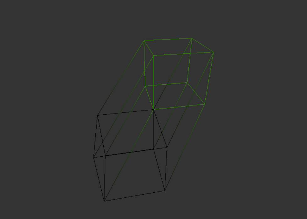
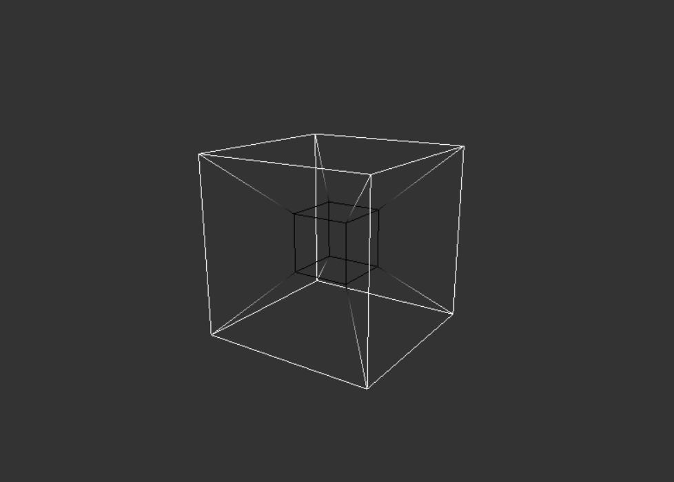
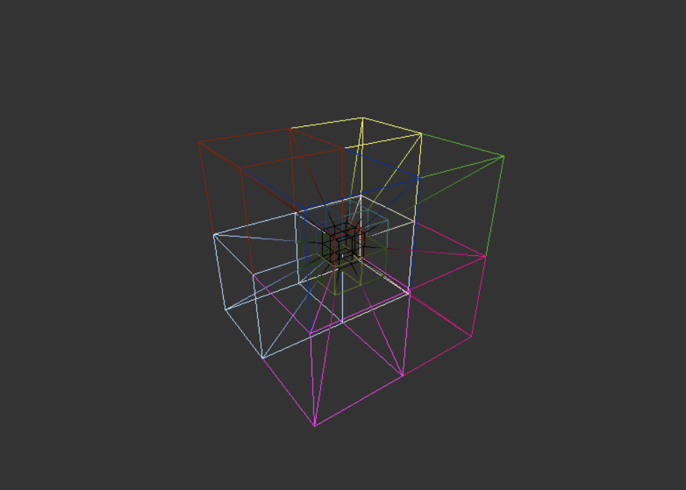
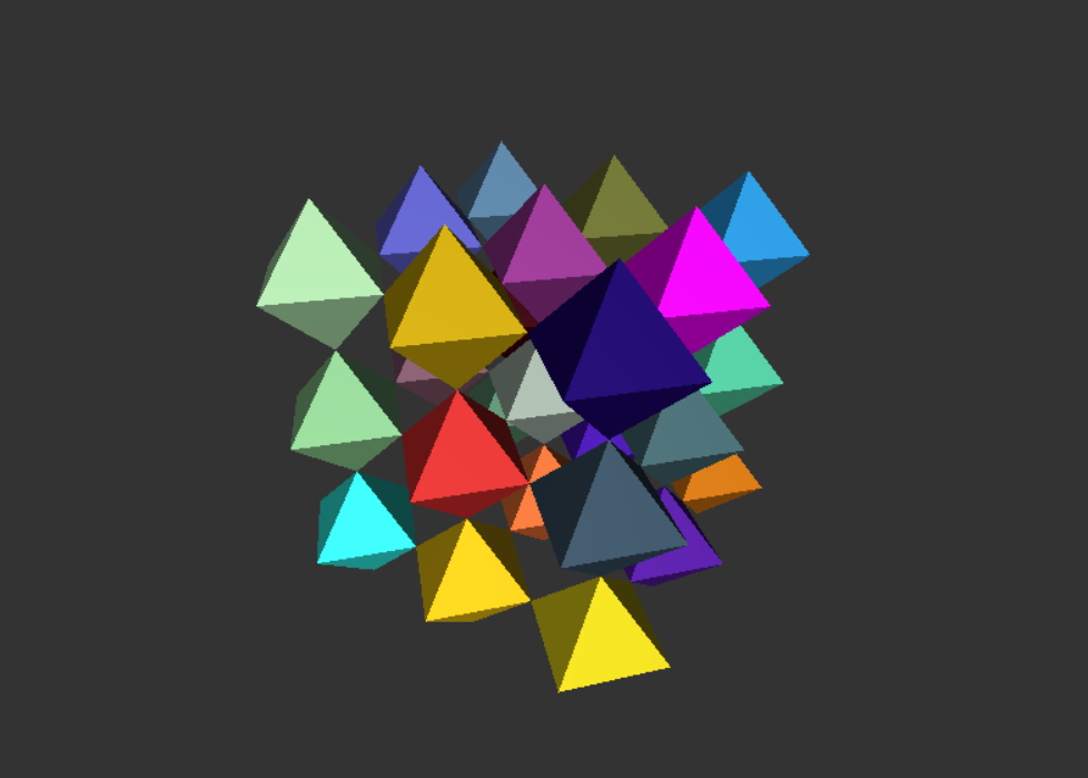
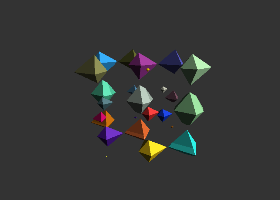
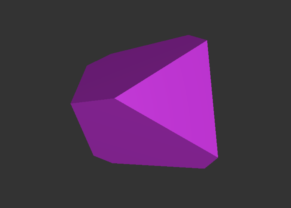
Two different methods of visualisation were implemented, a wireframe projection using 5x5 transformation matrices, similar to how 3D projection is performed, and a 3D cross-section, using the geometry shader.
What I Learnt
Throughout the project, I learnt a great deal regarding 4D geometry, different ways of visualising higher dimensional geometry, as well as some of the mathematics than underpin 4D geometry. This has encouraged me to continue investigating various ways 4D visualisation could be extended. I have also expanded my knowledge of the OpenGL API, including additional primitives that I was not aware of and various use cases for them, as well as use of the geometry shader. This knowledge can also be taken outside of the scope of this project and applied in future projects.
Video
Implementation
Representing Vertices
- 4D vertices are represented in C++ as a Vector4 and transformed by a Matrix5.
- However, the GLSL shaders do not support a mat5 type, therefore the transformation matrices are represented in GLSL as a static array of 25 floats, with functions for required operations.
Wireframe Projection
- Similar to 3D projection using transformation matrices, however, there is an additional phase to project the 4D vertices onto a 3D 'image plane'.
- Vertices are transformed from local space to world space using a 5x5 model matrix. These are then projected onto a 3D 'image plane' using a 5x5 projection matrix, followed by a manual perspective divide. The vertices are then transformed using the 4x4 view and projection matrices as part of the normal 3D rendering process.
- The wireframe is needed to allow the user to view inside the outer boundary (envelope) of the projection. This also simplifies the meshes used, requiring only a set of line primitives of 4D positions.
- Depth cueing is used to add additional sense of depth of the w axis. The further along the w axis a fragment is, the darker it becomes.
- 2 projection matrices were used:
- Oblique: Retains parallel lines at an angle to the image plane, but provides no sense of depth. This is done by adding the w coordinate to the x,y and z coordinates using a given factor.
- Perspective: Distorts parallel lines but provides a sense of depth using foreshortening. This is done by extending the 3D perspective matrix to add an additional dimension.
3D Cross-Section
- Similar to how an MRI scan takes 2d 'slices' of a 3D object, this renders a 3d 'slice' of the 4D object.
- Mesh data formed of tetrahedron shaped primitives. This is achieved using the Line Adjacency primitive.
- Geometry shader used to calculate the intersection of the object and plane. This splits each primitive into triangles and then lines.
- For each line, the distance from the 'plane' to each vertices is calculated. If they're on the same side, they are ignored. If a vertex is on the line, that vertex is emitted to the fragment shader. Otherwise, the distance of the intersection along the line is calculated and a new vertex is emitted by interpolating each attribute of the two line vertices.
Findings
- The wireframe projection was the quicker of the two visualisations. You can also see the entire object at once, but the projection can't display surfaces of the object, as such, it can only present the position and colour of the vertices.
- The 3D cross-section was slower as the program had to calculate new vertices for where the cross-section occurs. You can also only see a section of the object and can be difficult to work out the shapes of the cells that make up the object. However, this renders the object surface, allowing possibility of lighting, textures and reflections.
Future Work / Possible Extensions
- The first aspect I will extend is to include additional graphical techniques, such as the use of 3D textures, skyboxes and possibly bumpmaps, in particular with the cross section approach.
- I would like to investigate alternative methods of visualisation, as this project only implemented two. In particular, several approaches could be implemented using ray marching.
- I would like to add some simple physics/collision detection to the program, extending it to a simple game similar to Meigakure or Brane (previously tetraspace).
- I would like to try to implement this within an existing engine, such as Unity or Unreal Engine.